1.1. K18 Dev3.0 Board Introduction
Kamino18 Dev3.0 is a reference solution for smart speaker products. It contains main board and sub board two parts. As the below picture:
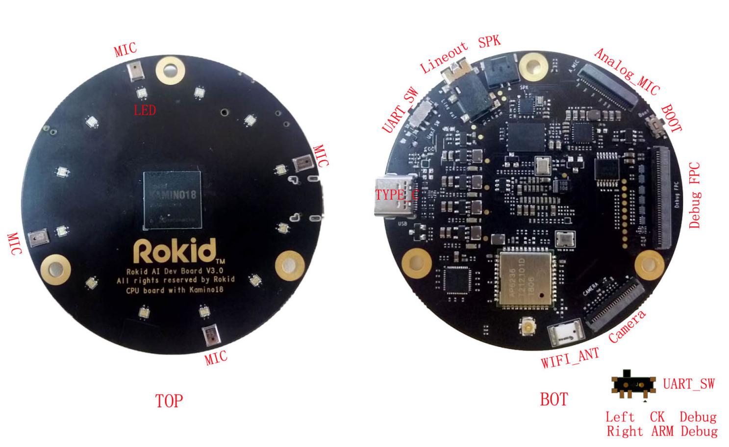 Main Board Diagram
- Lineout: Stereo headset
- SPK: Speaker 3.2w
- Analog_MIC: socket which can connect analog MIC daughter board
- BOOT: Boot key
- Debug FPC: socket which can connect Debug daughter board
- Camera: socket which can connect 2M Camera(OV2640)
- WIFI ANT: socket which can connect external antenna
- TYPE_C: ADB debug interface and usb power supply
- UART_SW: SW switch; switch to left, mcu uart output; switch to right, arm uart output;
- LED: 12PCS RGB LEDs
- MIC: 4 DMICs

Debug sub board Diagram
- IR: Infrared ray receiver
- USB HOST: Usb host interface
- DEBUG: USB UART converter for MCU and ARM debug
- UPGRADE(BOOT): The key for Image burning
- PWR(NC): Reserved key
- VOL-: Volume minus key
- VOL+: Volume plus key
- MUTE: MIC Mute key
- RST: System reset key
GPIO: GPIO extension
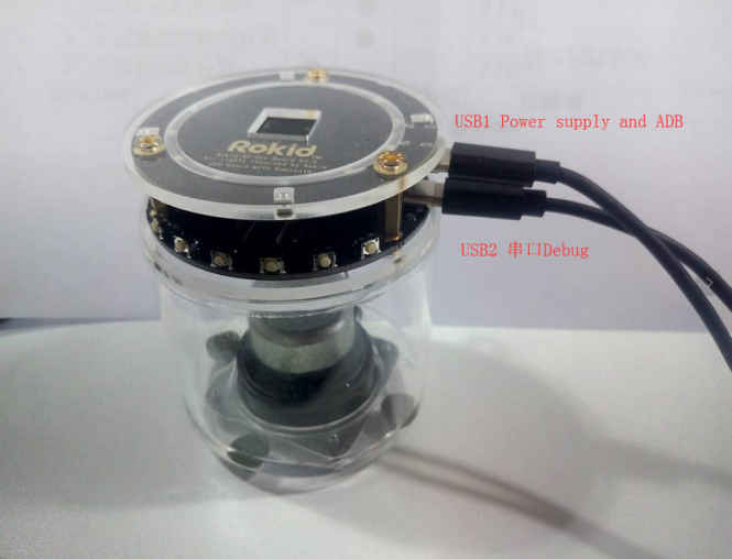
 USB Cable Connection Diagram
USB1 power supply and ADB,
- USB2 UART Debug, need install FT232 driver on PC, which can’t provide power supply for K18 DEV3.0
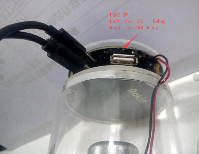
- UART SW, Left for CK Debug, Right for ARM Debug.